 |
| Figure 1: Two Types of Broadband Antennas: Planar Spiral and Log Periodic (Copyright Jonathan Becker) |
In order for an antenna to be frequency independent, they must follow Rumsey's Principle as noted in Kraus' antennas text [1]: the antenna shapes are only specified in terms of angles. Rumsey realized back in 1949 that a self-complimentary antenna (i.e., planar antennas that has a metal area congruent to non-metal areas) has a constant impedance at all frequencies. Balanas [2] also noted that in order for an antenna to be congruent, its frequency properties must not change if the antenna is rotated by an angle C (in the antenna's plane). Of course, the planar antenna needs to be extended out to infinity in order for it to be truly self-complimentary. In other words, there such antennas do not exist, as all antennas have finite physical sizes.
However, there is a loop hole that allows Rumsey's principle to apply. All antennas have RF currents that propagate along the surface of the antenna and create electromagnetic energy that is radiated. As long as the surface current dies off to zero at the end of the antenna (whether it be a metal patch, tube, or wire), the antenna can be terminated after the surface current is zero. Truncating the antenna would cause negligible effects to its frequency properties.
The Planar Spiral Antenna is one such antenna that whose currents die off by the end of the spirals. The antenna radiates normal to the plane (i.e. out of the screen of Figure 1). The planar spiral can have multiple arms, but two arms is common. In addition, there is another type of spiral antenna called the conical spiral. It is similar to the planar variety, but the metal is spiraled along a dielectric (i.e. plastic) cone.
In addition, I find the log-periodic antenna to be interesting. It is a broadband antenna, but it is not truly frequency independent according to Balanis [2] because it is specified in terms of angles and spacings between antenna arms. Any antenna whose structure can be defined as a periodic function of the log of the radial distance r (in spherical coordinates) from the origin is a log-period antenna. Log-periodic antennas are commonly used as TV antennas because they can be designed to operate over bandwidths of hundreds of MegaHertz to tens of GigaHertz.
I find it interesting how log-periodic antennas operate and achieve wideband characteristics. Unlike the Yagi antenna that are fed at a driving element and have multiple parasitic elements, all elements in a log-period antenna are electrically connected. I've indicated several important characteristics of a log-period antenna in Figure 2 below.
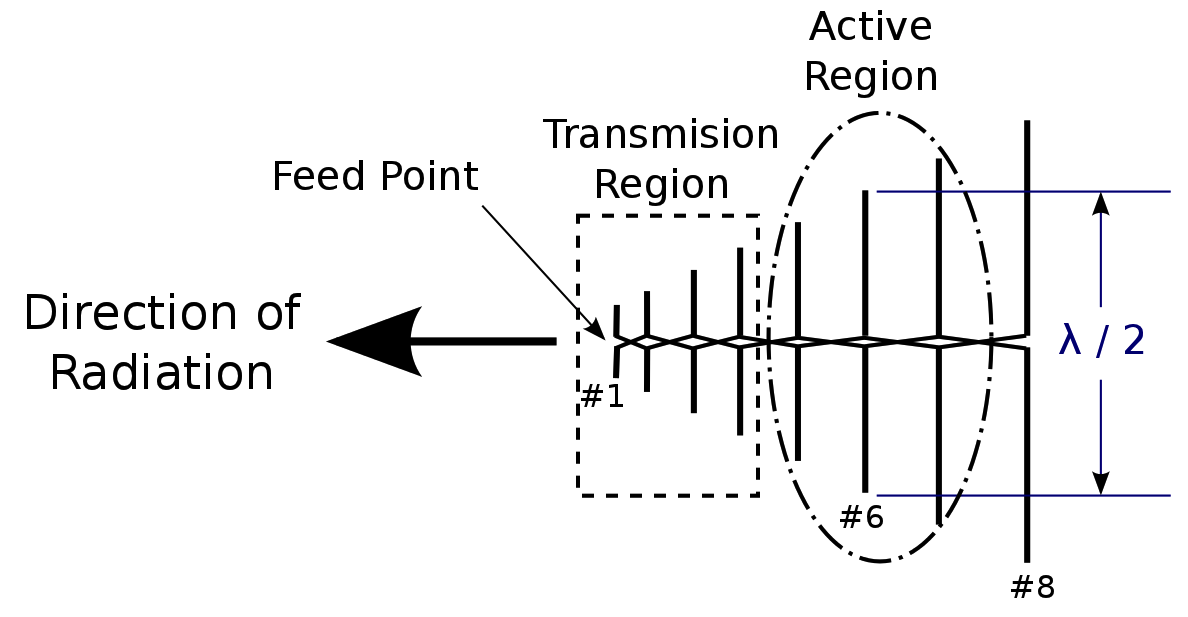 |
| Figure 2: An Example Log-Periodic Antenna with Regions of Interest Shown (Copyright Jonathan Becker) |
In my own research, though, I'll likely use a printed planar broadband antenna, as wire antennas take a lot of space. It is possible to design and build a printed circuit log-periodic antenna, so I will consider designing such an antenna. However, it is too early for me to finalize what antenna(s) I will use for my next anti-jamming antenna array. I plan on it later this Fall, and I am currently in the proposal / planning stage to define what remaining research I will do to write my PhD thesis and to complete my PhD.
Best,
Jonathan Becker
ECE PhD Candidate
Carnegie Mellon University
Q9RFJA4YN7VQ
References:
[1] J. D. Kraus. Antennas, 2nd ed. Electrical Engineering Series. McGraw-Hill Higher Education, 1988.
[2] C. Balanis. Antenna Theory: Analysis and Design. Wiley, 2012.
No comments:
Post a Comment